 Español
Features
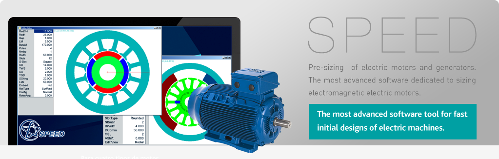
- The cross-section editor. The user can modify the lamination geometry and quickly understand the relationship between design features and particular performance characteristics, an almost lost art which used to take years to learn.
- The graphics winding editor lets the user understand winding configurations, modify the winding, or build custom windings. It also displays the airgap MMF distribution and all its harmonics graphically and in tabular form.
- The template editor is for editing non-geometric parameters including those of the drive. It includes wire tables and databases for steels, permanent magnet materials, carbon brushes, and power semiconductors. These databases can be customised and extended by the user. On-line help is available.
- The design calculator evaluates the design and performance data, including a thermal model, at a given speed and load. In most cases this takes only one or two seconds, computing as many as 500 output parameters. Speed is the key feature: with no waiting time, the user maintains concentration and progresses quickly. SPEED software doesn't do the engineer's job: it eliminates calculation time and adds information that can hardly be calculated by hand.
- The "SPEED sheet" documents all the calculations, while the ranging facility varies parameters automatically (e.g. to get torque/speed curves). Any output parameter can be graphed against any input parameter, permitting an unlimited range of detailed studies, and rapid refinement and optimisation.
- Graphical output includes waveforms of current, torque, speed, flux densities; and plots of radial forces and other specialised parameters.
-
For detailed simulation of the drive and its digital control, parameters can be passed from SPEED software to a specialist simulation program such as PORTUNUS.Dynamic simulation is included in all SPEED programs. Drive circuit topology and control strategy are limited to a fixed number of options, sufficient to ensure a good motor design that is compatible with the drive. Work is in progress on software links that will make this semi-automatic, by means of library modules and other specific data formats. As with finite-element links, those with dynamic simulation programs like PORTUNUS help create a "designer's workbench" of extraordinary power and efficiency. In the future such tools will be more important as the design of integrated systems products becomes more sophisticated.
- Automatic links to FLUX finite-element software are used by SPEED software:
- to automate routine finite-element calculations and save engineering time
- to pre-optimise designs so that finite-element software is used only for the last stages of refinement
- to prepare meshes and set up the problem for finite-element solution of advanced problems in electromagnetics, thermal management and stress analysis
- to refine parameters calculated by SPEED software, increasing accuracy and confidence
On some projects the links have saved months of repetitious work in the optimisation of very demanding motor designs. SPEED links use the scripting language of the finite-element software.
In the Unimesh approach to meshing, SPEED software generates the coordinates of nodes along all region boundaries, including all boundary conditions. Meshing is controlled by special graphics editors within the SPEED software, exploiting the expert knowledge of the motor engineer. Unimesh produces stable, accurate solutions faster than standard or adaptive meshing techniques
SPEED software is backed up by the world-wide direct Technical Enquiry Service, which provides technical assistance with designs; custom features and new calculation procedures and consulting on motor design and theory.